As an instructor in a small university theatre department, I am always on the look-out for cheap or free software to recommend to my cash-strapped students. In the University of Wisconsin Oshkosh Theatre Department, we use and teach Vectorworks, but this program is often beyond the means of our graduating seniors. So I was interested to discover a drawing program that is available as a free download, yet is quite capable of serving as a basic 2D CAD program. The program is the drawing module of Openoffice.org.
OpenOffice.org is an Office Suite which based on the Sun Microsystem's StarOffice suite. It was developed as an Open Source project by volunteer programmers in the open source community. OpenOffice is well know as an alternative to commercial office suites, and is available as a free download from OpenOffice.Org (www.openoffice.org); the latest version is 2.0.3. OpenOffice is available for a number of operating systems, including Windows, Linux, and Mac OS X (using X11).
The program contains several quite capable modules: a word processor, a spreadsheet program, a presentation program, and even a database program in the latest version. It also contains an extremely capable drawing program called "Draw". I have found that Draw can be used as a basic 2D CAD program. I suspect the Draw module was really meant for businessmen creating graphics to be used in the presentation module (similar to Powerpoint), but it has enough flexibility to allow the creation of CAD draftings as well. Draw is capable of creating and modifying vector graphic objects, and can do so in scale. It can also do layers, a very useful tool in CAD. It doesn't have all the bells and whistles of a true CAD program, but it can do quite a good imitation with the use of a few work-arounds. The purpose of this article is to provide some of the work-arounds I've discovered to make Draw do what you wish, and to create perfectly adaquate drawings quickly and easily with a free program, instead of using one costing hundreds or even thousands of dollars. While it will never replace Autocad, Vectorworks, or WYSIWYG, it can still be a useful tool, especially for those on a limited budget who can't afford the higher end options, but would still like to make CAD drawings.
It helps to have some idea of what Draw can and cannot do:
Draw can work in a variety of units, but unlike a true CAD program, it cannot understand mixed units. It can work in feet, or inches, or meters, or millimeters, etc., but it cannot work in Architectural scale. i.e. "feet & inches" at the same time. It also doesn't understand fractions except as decimal fractions. There is a "manual" work-around, which will be presented later.
Draw works "in scale", but the scales must be expressed in the form of a ratio. There are a number of standard scales which can be selected (found under the menu item Tools|Options|OpenOffice Draw|General), e.g. 1:1, 1:2, 1:5, 1:10 etc. If you wish to work in an Architectural scale, you must convert it into a ratio, then manually enter it into the Drawing Scale option box. For example, if you wish to work in 1/4"=1'-0" scale, you must convert it to a ratio, in this case 1:48, and manually enter that figure into the option box. The scale chosen applies to all layers of the drawing, and to any new drawings you create until it is changed again.
Draw does not "scale" objects on the drawing automatically when the sheet scale is changed. If you change scales from 1:12 to 1:24 (1"=1'0" to 1/2"=1'-0") then the objects of the drawing will "dimension" twice as big. A 12 ft. line in 1" scale will measure 24 ft. after changing scale to 1/2". The workaround is to scale the objects manually, but this must be done as a separate step; it is not automatic.
A major limitation is the inability Draw to properly "tile" large drawings to accommodate the printer paper size, while still printing ALL of a large drawing. Basically, Draw seems to pass the tiling process off to the printer, instead of doing it internally as most CAD programs do. With the printers I've tried, I have found that I lose about an inch of graphic on the second and subsequent sheets when a "margin" is created where data should be. I have worked out a work-around involving Adobe Reader that seems to deal with this.
Draw doesn't do custom Symbols or Blocks in the way many CAD programs do, BUT Draw does do Groups, and these can be stored in the "Gallery", a sort of clipart library, and then inserted into drawings like Symbols.
Draw is mouse-driven. It doesn't seem to have a "command-line" mode. If you are used to Vectorworks, this won't be much of an issue, but if you are an Autocad fan, it could be a problem.
Please understand that this "tutorial" is based on the idea that you already have some familiarity with CAD programs and are trying to make Draw behave like one. Hopefully, you can follow the rest of this. If not, I apologize in advance. Also, rather than write a "traditional" tutorial, I have described the steps I took to set up the program to make it convenient for me as an example. Your choice of options will probably vary.
Draw has an amazing number of capabilities and options. As the name suggests, it is a drawing program, but has enough options to allow it to be customized into a CAD program. How easy it is to use depends on how you set it up for yourself.
Setting the Draw Default Options
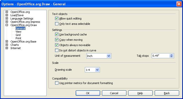
To begin with, you should set the global options for Draw. This is where preferences are set that apply to new drawings, and where these preferences are changed for an existing drawing. Some of these options also have Toolbar buttons available for selection, but some do not.
First open 'Tools|Options|OpenOffice.org Draw|General". Here is where you set the Unit of Measure, for example as "Inch" or "Foot". Set the desired scale, but remember to figure it as a ratio. Again, you can select a preset ratio or, if you wish to work in a scale like 1/4"=1'-0" scale, you must convert it to a ratio, in this case 1:48, and manually enter that figure into the option box.
Also select "Allow Quick Editing" and "Copy when moving". The first will allow you to edit displayed dimensions to "correct them" or to enter them in a different format (such as with mixed units), and the second will make creating multiple copies of objects easier. This makes it easier to make copies of objects in some cases..
You can select other options under View, Grid, and Print. Some of these are also available in the Toolbars.
Setting up the Toolbars
When you open OpenOffice Draw for the first time, you will probably see three toolbars. The Standard bar is at the top, and includes most of the typical file tools, e.g. New File, Save, Print functions, Help, etc. Under this is the Edit bar, which changes context as different tools are selected, and the Drawing bar, located on the left side of the screen, which contains a selection of drawing tools. Many of the tools have fly-out menus attached which offer more tool choice. Most of these can also be dragged off to become floating menus or docked elsewhere if you prefer.
You can also add Toolbars to the page by going to the Menu bar at the top of the screen and selecting "View|Toolbars". For my purposes, I have selected the Standard bar, the Drawing bar, the Line and Fillings bar (displayed on the Edit bar), and the Options bar. The Line and Fill bar shows line weights and fill types, and the Options bar displays Snap types, Text select, and Rotation options. Sometimes I dock the Zoom bar at the top as well. This gives me quick access to the tools I use most. You may choose other tools to dock instead. You can also customize the toolbars to display the buttons you use most.
There are a few other options I also turn on. Under the View menu, I turn on the Page pane, the Status bar, and the Ruler. The Status bar is where the size of objects is displayed as you draw them, and I like the Rulers as size guides. More on the Page pane below.
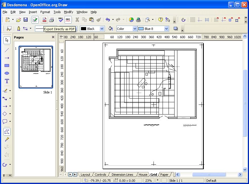
Here is the drawing desktop as I've described it so far, with an 11x17 drawing sheet displayed. Creating the drawing sheet is the next step.
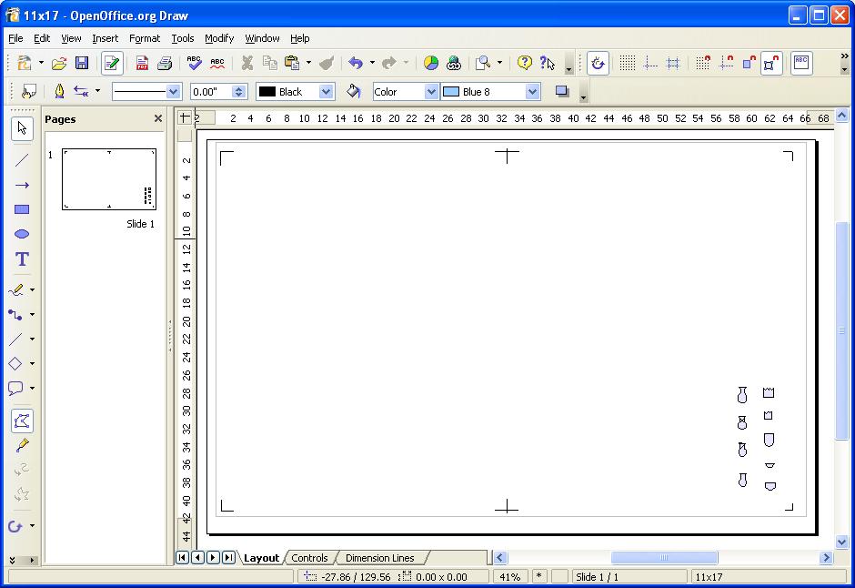
Setting up the Drawing
By default, Draw opens with a page based on your printer's default paper size, probably _Letter 8.5"x11"_ in the US. CAD drawing are often bigger, especially in Theatre. There are two work-arounds, depending on the drawing you wish to do.
If you wish to make a working drawing in Orthographic perspective with multiple views, AND each individual view can be fit to a single letter-size sheet, then the simplest approach is to open a new document, and create multiple Pages. Right-click on the Pages pane and click "New Page". Each view is a separate page, but are all part of the same drawing file. A thumbnail for each page is displayed in the Page pane, and you can move quickly from page to page by clicking the thumbnail. Use each page as a "viewport" in a larger sheet. For instance, if you set the pages to Landscape format (under "Format|Page..."), and place the Front view on Page 1, Side view on Page 2, Top view on Page 3, and the title block, drawing keys, and/or parts lists on Page 4, you can easily assemble them into a completed 16"x22" working drawing.
This method will work for drawing where the views can comfortably fit on printer-size pages. But if a view is too large to fit on one, and runs over onto two or more pages, as often happens with ground plans, then another approach is needed. Real CAD programs can break up a large drawing into Tiles, and prints them so the complete drawing can be assembled from the tiles. OpenOffice can create tiles as well, but the function doesn't work too well, at least when I've tried it. There ends up being a margin out of the middle that is missing on the printout. So I've come up with an alternative approach that uses Draw to create the drawing, and Adobe Reader to print it.
The work-around in this case involve an included tool that makes OpenOffice very powerful indeed. The suite can directly export files in PDF format from any of its modules, including Draw. It does not require Adobe Acrobat to accomplish this. Unlike desktop printers, PDF sheet sizes can be any size you wish. So, start by formating the "page" to the size you need.
First, set up you Drawing Units and Scale preferences as above. Then set the drawing size. Go to the menu item: "Format|Page| Page tab". If you can select a standard page size as displayed, go ahead. Otherwise, select "User" and enter the desired page dimensions. I'd suggest using multiples of 8"x10"(plus margins). For now, assume 11x17 inches, which allows for two 8x10 sheets plus 1/2" margins.
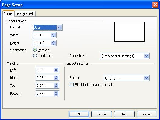
For now, enter Width-17" and Height=11" and click "OK". You can leave it in Portrait orientation. You should see a sheet of the dimensions selected. Click OK.
Pre-setting pages for Printing
As stated earlier, Draw doesn't always tile printer sheets very well. However, Adobe Reader provides an option that can fix this problem. To do use it, however, I set up a template to allow later selection of sheet-size areas of the drawing. I drew continuous rectangles 8"x10" on the sheet, then made "T's" and "L's" at the corner of the rectangles as guides for later "drag-and drop" selection in Adobe Reader. (It helps to temporarily set the scale to 1:1, the switch back when done.) I then deleted the guide-rectangles, and saved the result as a template. It looks like this:
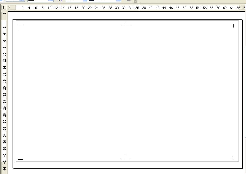
I then use the template as the start of a drawing of a given size.
Drawing with Draw
A few words about using the Drawing tools. If you have used a CAD program or any basic drawing program before you will find much of Draw familiar. Using the drawing tools is very much like many CAD programs or other Drawing programs. Select a tool, then click and drag with the mouse to create an entity. Draw does not always "stay" in the mode you were just in as you draw. For example, most CAD programs keep a particular tool active (such as the Line tool) until you select another. With Draw, you must select the Line tool to draw a line, the re-select the Line tool again to draw the next line, and so on. However, if you double-click a tool, it will stay selected until another tool is chosen. When you select an existing entity or multiple entities, the entity handles and vertexes will be displayed, and can be used to move, copy, resize, or rotate them. The location and size of the entities will be displayed in the Status bar relative to the drawing grid, in the Units and Scale you set earlier.
Some entities, like lines and irregular polygons, can be drawn diagonally, but the displayed size is relative to the position of the ends on the X-Y axis. If you want the actual length to be displayed, draw the lines along an axis. Other entities, like rectangles, can only be drawn on the axes. But they can then be rotated to the desired angle and rotated into position.
As you learn, be sure to check out the help files. Draw can do a lot and the Help files are extensive, and will show you where and how to do things.
Printing Large Drawing Tiles
Once you have drawn (and saved) your large size drawing, the first step in printing it is to export it as a PDF file. This is very simply done. Either go to "File|Export", or just click the Export Directly as PDF button on the Standard toolbar. Make sure the selected file type is set to PDF, give the file a name, and click OK. That's it! You can now close Openoffice.
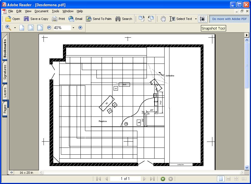
Now find the PDF file wherever you saved it, and open it in Adobe Reader. You should see your drawing, complete with the alignment marks made under "Presetting pages for Printing" above. Adjust the Zoom so you can see at least one 8x10 section. Click on the Snapshot Tool (it looks like a Camera). Carefully click-and-drag a selection rectangle over the desired set of alignment marks. You will see a dialog box saying "The selected area has been copies to the clipboard." Click OK.
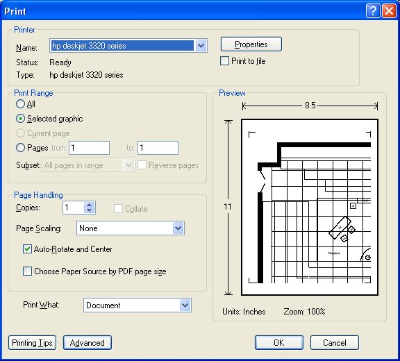
Now go to "File|Print" You should see a thumbnail preview of the selection. Print Range should have "Selected graphic" selected, and it should say "Zoom 100%" under the thumbnail. Click OK, and the tile should print.
Go back to Adobe Reader, and repeat the process with each 8x10 area. Once you have printed them all, you can trim and tape the tiles together as with any other CAD program.
2023 UPDATE: Adobe Reader has really made the snapshot tool hard to find in the 2023 version of Reader, but it is still there.
Open the PDF in Adobe Reader. Now go to the OS Menu bar for Reader at the top of the screen (not the menu bar inside the app window). Select Edit > Undo, Redo, More > Take a Snapshot. You can then select by dragging the curser over the area to be printed. You will get a message that the selected area has been copied. Click the Print icon in the upper right of the Reader. In the Print dialog that opens, select “Actual Size”, then [Print].
Proceed with the other panes in you drawing as above.
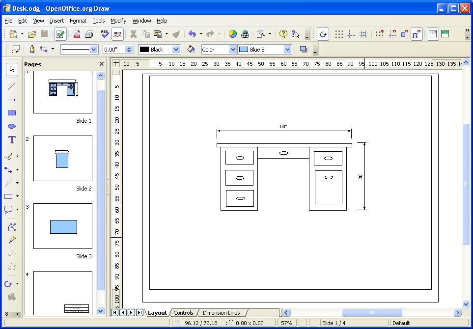
Some entities, like Rectangles, Ellipses, and Filled Polygons, are filled by default with a Color, probably "Blue 7". Most CAD drawings are Black and White. There are several options available. You can change the fill color to White. You can set the Color selection to "Invisible", which makes the entity "unfilled". Or, you can draw in the entities with colored fills, then before printing go to "View|Color/Greyscale" and select Black and White. The colors are still set, but not displayed or printed.
Part of the utility of CAD drawings is that it is easy to accurately dimension objects. Draw can also do dimensions, and will express the dimension in the selected unit and scale. However, because it does not do "mixed" units or traditional fractions, all dimensions are in one unit with decimal fractions. There is a work-around. IF you selected "Allow Quick Editing" under 'Tools|Options|OpenOffice.org Draw|General", you can "fix" a dimension. Lets say you have a dimension that reads "12.33 ft", and you wish to express it in Architectural format, as 12'-4". Simply double-click on the dimension text. This activates a text box for the selected text. Type in the text in the form you want: i.e. 12'-4". Click any other tool icon, and the change is entered. And yes, you can use this technique to tweek a dimension or even to make it "lie"!
Draw doesn't do custom symbols as such. For that you need a real CAD program. But there is a work-around. For the most part, symbols are a type of group entity, and Draw does do Groups. Start by setting a new drawing to the desired scale, then create the symbols you need using the appropriate drawing tools. For example:
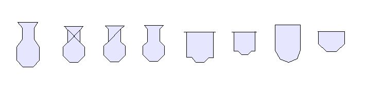
I
built these lighting "symbols" in 1/4" scale using the
Filled Polygon tool, and also with the Line tool (for the 6x16 and
the 6x12 symbols). You may note they are only approximations of USITT symbols,
but least they were easy to draw! Then I grouped the multiple entity symbols
using "Modify|Group", and saved the drawing to be used as a
reference drawing.
To use the symbols in another drawing, create or open it, then open the symbol reference drawing. Select and copy the "symbols", go back to the "other" drawing, and paste them into it. This will give you one copy of each symbol. (You may wish to use them to create an Instrument key.) To make more or make multiple copies, you can use several techniques. You can use a Select/Copy/Paste procedure, but when you do, the copy is placed directly on top of the original, and can be dragged off while selected. A faster method of to use the "Move to Copy" function. For this, make sure you have "Copy when moving" selected under 'Tools|Options|OpenOffice.org Draw|General". Then on the drawing, select the "symbol" you wish to copy, hold down the Ctrl key, then click-and-hold one second or so, then drag a copy off the original, leaving the original in place. You can keep doing this until you have enough copies. The copies can then be moved and rotated to wherever on the drawing you want them. You can also duplicate an object by selecting it, then go to "Edit|Duplicate", and enter the number of copies you want.
Here is another trick. Lighting symbols are usually numbered with the Instrument number. An easy way to do this in Draw is to go to the Options toolbar and turn on "Double-click to edit Text". Now when you double-click an entity, Draw will open a Text-box at the center of the entity. Format size and font of the text on the Text Edit toolbar, and enter the desired unit number. The number will rotate with the object, so you may not want to use this feature on inverted entities! You will also need to place any other instrument data manually on the plot. None of it is associated with a "symbol", but can be grouped with it if desired.
Of course, Draw does lack the embedded database tool found in Vectorworks Spotlight or LD Assistant. If you need that, you won't get it for free.
You will recall that the "symbols" above were created in 1/4" scale. They do not re-scale automatically when the drawing scale is changed. But they can be resized manually. First, make a copy of the object to be resized. Select it or them, and go to "Format|Position and Size" , or click the "Position and Size" icon on the Drawing tool-bar. Make sure "Keep ratio" is checked, then double either the width or height to increase the scale to 1/2", or halve it to decrease the scale to 1/8". Click OK, and the size of the symbol will scale accordingly. for use in a 1/2" (or 1/8") scale drawing.
Obviously, Openoffice Draw lacks many of the features of a high-end CAD program. But if your needs are not extensive or frequent, but you want access to a simple, free and legal CAD program, Draw is definitely worth checking out.
Since this article was originally posted, I have received suggestions from several people about using OpenOffice Draw for CAD.
From Chris Walden comes the suggestion to create a Gallery "theme" for lighting symbols, and use that as a symbol library. This is a better approach than the "paste from another file" method outlined above.
The Gallery is basically a Clip-art collection, but in Draw you can save Draw objects there as well. To begin, open or create a Draw document with the symbols you wish to convert. Then open the Gallery, either by clicking on the Gallery icon, or using the "Tools|Gallery" from the menu bar. This opens the Gallery in a frame above the drawing pane. You will see a number of built-in Gallery "Themes" listed, each a collection of objects, such as Background, Bullets, and so on. Click on "New Theme", which will create and open a new theme document in the window. Give it a name, e.g. "USITT Symbols".
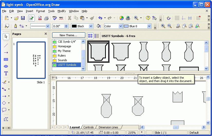
Placing symbols into this Gallery Theme is quite easy. Select a drawing object, then "click and hold" the object for two seconds. Then drag the object into the Gallery window, and it will be added to the Theme. You can then re-name the symbols as desired by right-clicking on it in the Gallery (Control- click on a Mac), select Title, and then give it a new name.
Using the new symbols is even easier. Open the Gallery, select the desired theme, then drag the symbols onto your drawing to wherever needed.
Since the previous article was written, OpenOffice.org has continued to develop and grow. OOo has always included the ability to export a file in PDF format. One could also import a PDF drawing file into Draw by the Copy/Paste method. Unfortunately, this method usually captures only the "bitmap" portion of a PDF file, and so brings the PDF into a drawing as an image file (i.e. a PNG) rather than as a vector drawing. Also, the image so imported is often slightly altered in size from the original's scale. You can resize the image until it is approximately correct using the "Position and Size" tool, but the image itself cannot be directly edited otherwise. OOo could also import data from a DXF fle (text format but not binary file), but the size was often severely altered from the original, and again needed adjusting.
This limitation has been somewhat elliminated in OpenOffice.org version 3. With OOo 3, you can now import and edit both the vector data and the text data from a PDF that contains vector information. The advantage of this is that the vector data is accurately rendered in the same scale as the original PDF, and you have the ability to edit the vector and text data once it has been imported into the ODG file, just like native objects in the drawing.
To accomplish this, you will need both OOo v.3 and the "Open Office PDF Import Extension". Some versions of OpenOffice (e.g. NeoOffice for Mac) come with the extension already installed. If you do not already have it installed, you can search for and add it using the Extension Manager under the Tools menu.
Once the extension is installed, importing a PDF into a drawing is easy. Simply open Draw, then use the File|Open dialog to navigate to the PDF drawing. Select it and click "Open". The vector and text data of the drawing will be imported into a new ODG drawing. You may now proceed to edit the imported objects. The new drawing is a Draw file, and can be saved as an ODG file.
Exporting the file for use in another program again involves exporting the drawing as a PDF file, just as before. The built in PDF generator can export the file as a vector based PDF. This can be imported into other CAD programs (e.g. Vectorworks) that have have the ability to import PDFs. Thus, by using PDF files as the intermediary format, one can now import and export drawings between Draw and other PDF capable CAD programs in both directions.