Electricity is the flow of electrons from one place to another. Electrons can flow through any material, but does so more easily in some than in others. How easily it flows is called resistance. The resistance of a material is measured in Ohms.
Matter can be broken down into:Since electrons are very small, as a practical matter they are usually measured in very large numbers. A Coulomb is 6.24 x 10¹⁸ electrons. However, electricians are mostly interested in electrons in motion. The flow of electrons is called current, and is measured in AMPS. One amp is equal to a flow of one coulomb per second through a wire.
Making electrons flow through a resistance requires an attractive force to pull them. This force, called Electro-Motive Force or EMF, is measured in volts. A Volt is the force required to push 1 Amp through 1 Ohm of resistance.
As electrons flow through a resistance, it performs a certain amount of work. It may be in the form of heat or a magnetic field or motion, but it does something. This work is called Power, and is measured in Watts. One Watt is equal to the work performed by 1 Amp pushed by 1 Volt through a resistance.
AMPS is amount of electricity.
VOLTS is the Push, not the amount.
OHMS slows the flow.
WATTS is how much gets done.
There are 2 standard formulae that describe these relationships.
Ohm's Law:
Where
To express work done: Power formula (PIE Law):
Where:
P = IE
This law is often restated in the units of measure as the West Virginia Law:
W = VA
for
Watts = Volts x Amps
All this is important because all electrical equipment has a limit to how much electricity it can handle safely, and you must keep track of load and capacities to prevent failure, damage, or a fire.
For example, a lamp is rated at 1000 w. @ 120 v. That means that at 120 volts it will use:
A common shortcut is to use 100 v. instead of 120. This makes calculating easier and builds in some headspace. So:
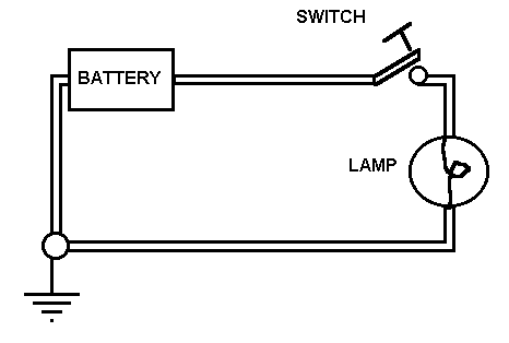
The simplest circuit has a power source, like a battery or outlet, a wire running from the "hot" side to a "load", then a wire from the load back to the power source. There is also usually a switch to "open" or "close" the circuit. The load will function only when the circuit is closed or complete.
In more complex circuits where more than one load is connected, they may be either in series or in parallel. In a series circuit, current must pass trough one to get to the next. Voltage is divided between them. If one goes out, they all go out.
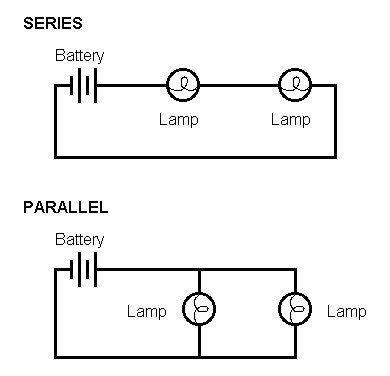
In a parallel circuit, each load is electrically connected to the source at the same point, each gets the full voltage simultaneously. If one goes out, the rest stay lit.
Most circuits are combinations of the two types. Circuit breakers and fuses are in series with the load, but multiple loads on a circuit are paralleled.
Circuit breakers and fuses can be placed in the supply circuit before the plug, as in lighting circuits, or between the plug and the load internally, as in most sound equipment, or both.
Cable, connectors, and circuits are all rated in amps according to size.
There are many types of cable, but the electrical code allows only certain types to be used. Stage use is very hard on equipment. Cable may be walked on, runover by scenery or vehicles, pulled and dragged, and pinched. The emphasis is therefore on flexibility and durability.
For single circuit used, ONLY type S or SO cables are permitted. Type S is a heavy-duty rubber covered cable. Type SO is a heavy duty Neoprene (synthetic rubber, oil resistant) covered cable. It must be a three wire cable, with black, white and green conductors. Type SJ, with a lighter weight rubber covering, is specifically NOT permitted. For single conductor feeder cable use, welding cable was once common is specifically NOT permitted. It must be Types SC, SCE, PPE or similar Entertainment and Stage Cable, which has an extra-heavy duty cover and very flexible wire inside.
| Wire gauge | Ampacity |
|---|---|
| #18 | 7 a. |
| #16 | 10 a. |
| #14 | 15 a. |
| #12 | 20 a. |
| #10 | 25 a. |
| #00 (2/0) | 300 a. |
| #0000 (4/0) | 405 a. |
Connectors allow temporary connections to be made and broken quickly and safely. Male connectors have exposed contacts. Female connectors have internal contacts inside an insulating shell with holes for plugging the two together. Think biology.
The male is always on the load side of a connection, the female on the line side; "the female has the power!"
parallel Blade (Edison): the standard household plug, this is found on much equipment but is not durable enough for stage lights. The standard configuration, two parallel blades and a U-ground, is rated at 15 a. only. Usually the"hot" terminal is copper colored and the "neutral" is silver colored, and the "ground" is green.
Stage Pin (a.k.a. NEMA designation, 5T-20): has round 1/4" pins, and is very durable. Most common dedicated stage connector. Rated at 20 a. The center pin is "ground", the outside pin nearest the ground is the "neutral", and the other is the "hot".
3-pin Twist Lock (a.k.a. NEMA L5-20): has three curved blades which are locked into the receptacle by rotating it 1/8 turn after insertion. Rated at 20 a. One blade has a tab bent towards center; that is the ground. The slightly larger blade with silver screw is "neutral", and the small blade with the copper screw is "hot".
Cam-locks: single wire connector for large wire, 2/0 or 4/0. Locked in place by rotating 1/2 turn after insertion. Comes in colors to indicate which leg is which. Rated at over 400 a. In most common size on stage. Also available in a mini-cam size for #1 cable, rated at 100 a.
Two-fers: Y-cord with one male and two female connectors, for plugging two devices into one outlet.
Three-fers: same thing, 3 females.
Adaptors: a male connector on one end and a female of a different type on the other. Used to plug a device into a different type of outlet.
There are broadly two form in which electricity can be generated, Direct Current and Alternating current. Direct Current is the type of electricity supplied by a battery. One terminal is positively charged, the other negatively charged, and electricity flows from one to the other, always in the same direction. However, while it is simple to make and control, DC does not travel well over long distances; it gets used up by the resistance in the transmission lines, and is gone before it gets to where it is needed.
Alternating Current also has a positive and a negative terminal, but the polarity and the direction of flow alternates many times per second. In the United States, electricity alternates polarity 120 times per second, or 60 full cycles per second, i.e. 60 Hz. AC can travel well over long distances, and so it the choice for power distribution lines.
There is no difference between amps or volts between AC or DC. Some devices can ONLY operate on one type of system or the other, but otherwise a volt is a volt.
Road shows and concert tours typically bring in their own lighting and sound rigs, which means their dimmer racks and sound distribution boxes must be tied in to a power source able to supply large amounts of current.
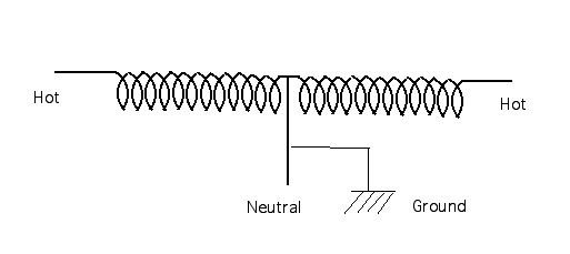
Power is usually generated at a distance from where it is used. It is supplied as 3-phase power at very high voltages.This allows many kilowatts to flow through fairly small conductors because amperage is effectively small. There are 3 hots, each 120 degrees out-of-phase with the next when their sine waves are plotted against each other, hence the term "3 phase". There is no neutral. This configuration is called Delta, and is the same type (at much lower voltages) use to run 3-phase motors.
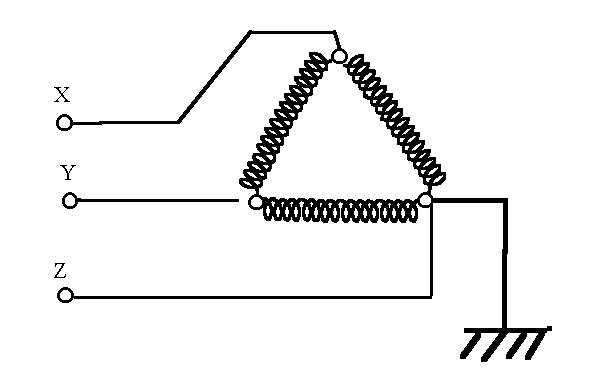
The power level is brought down through a series of substations. At each step transformers reduce the voltage and increase the amperage until it reaches the line transformers outside the building. At that point, the Delta service is converted to a Wye service, and is brought into the building at the "service entrance".
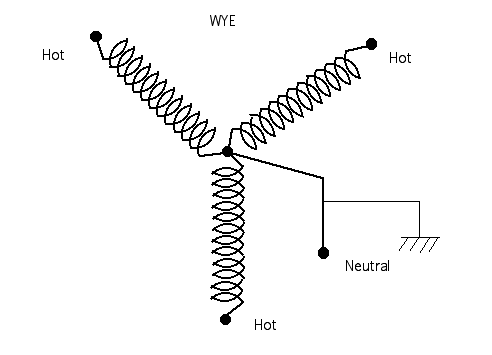
The Wye service has the same three hot legs, plus an electrical neutral created at the transformer. By this time in either Wye or Delta, the line voltage has been brought down to where each hot terminal is 120 volts above earth potential, called "ground", and in the case of a Wye service, each hot is also 120 v. above the Neutral as well. However, due to the geometry of the hot phases, there is a difference of 208 v. (not 240 v.) between any two hots in either type of 3-phase system.
This is different from the Single-phase system found in some older theatres, and commonly in private homes.
In this service two hots are drawn from each end of one phase of a Delta (hence Single phase), and a neutral created at the transformer. These are brought into the building at the service entrance. Between either hot and the neutral there is 120 v., just as in the Wye system. However, there is 240 v., not 208 v, between the two hots. Single phase is rarely found in industry, including theatre, because it is not as efficient for supplying the large amounts of power needed.
At the service entrance the Neutral of the Wye (or of a single phase) system must be bonded to a grounding system buried in the earth outside. It is VERY important that the ground and neutral NOT be connected at any other point, or an unsafe situation could be created.
When in comes to permanent commercial wiring, the Electrical Code requires that only licensed electricians do the work. However, the Code has an exemption for the Entertainment industry. "Qualified Personnel" are allowed to make TEMPORARY hookups to an electrical service. That means that a qualified stagehand can tie a portable dimmer rack to a distribution box, but cannot run permanent wires to that box OR install a PERMANENT dimmer rack. The key phrase is "Qualified personnel". Only stagehands have who been trained to do so are allowed to make hookups. The Code also grants another exemption to theatre not found in other industries. Theatre is allowed to use single conductors and connectors (that is feeder cable with Camlock connectors). But as it is VITAL that the connections be made in the proper order, only trained and qualified personnel are permitted to make those connections.
The distribution box where temporary equipment is tied in to the electrical supply is called a Company Switch, a Distro, or a "Bull switch".
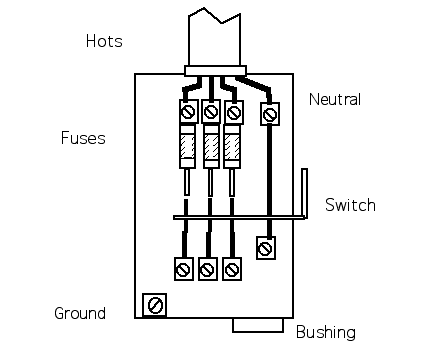
Inside the distro are lugs for connecting the wires. There are three lugs for connecting the "hot" wires, each of which is connected to a fuse or a circuit breaker. They are typically referred to as Leg A, B, and C; or leg X, Y, and Z. They may be black or marked with any color EXCEPT White, light grey, or green. There is also a lug for the Neutral, which does NOT have a fuse or breaker, which MUST be marked white or light grey, and a lug for the Ground wire, which is usually bolted directly to the metal distro box. (According to Code, the box and its conduit are suppose to be grounded, but if they are not, a separate grounding wire, marked with green, must be run to the box.) There will also be an access hole through which the temporary wires are passed. The hole should have a bushing to prevent the box from cutting through the insulation of the wire.
The proper procedure MUST be followed when connecting the cables, or an unsafe situation can occur. DO NOT TAKE SHORTCUTS!
When the feeder cables are connected to the dimmer rack or sound distro, and when the feeders are connected to the tails, CONNECT THEM IN THE SAME ORDER!, That is: first Green, then White, then the three Hots. Connect them with the power turned off but always treat them as though the power is on anyway. Someday it may be!
Also, NEVER PLUG THE HOTS IN FIRST! The equipment may try to close a circuit through two hots and put 208 v. through a circuit meant for 120 v., and destroy the equipment, or worse yet electrocute someone!
Many rigging motors are three-phase motor, using three hots and NO neutral. Occasionally a motor may run backwards. In that case, simply swap any two hots and the motor will run the other way.